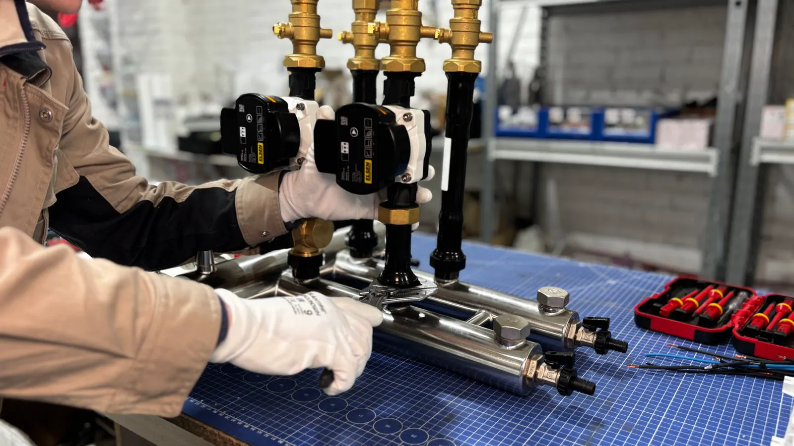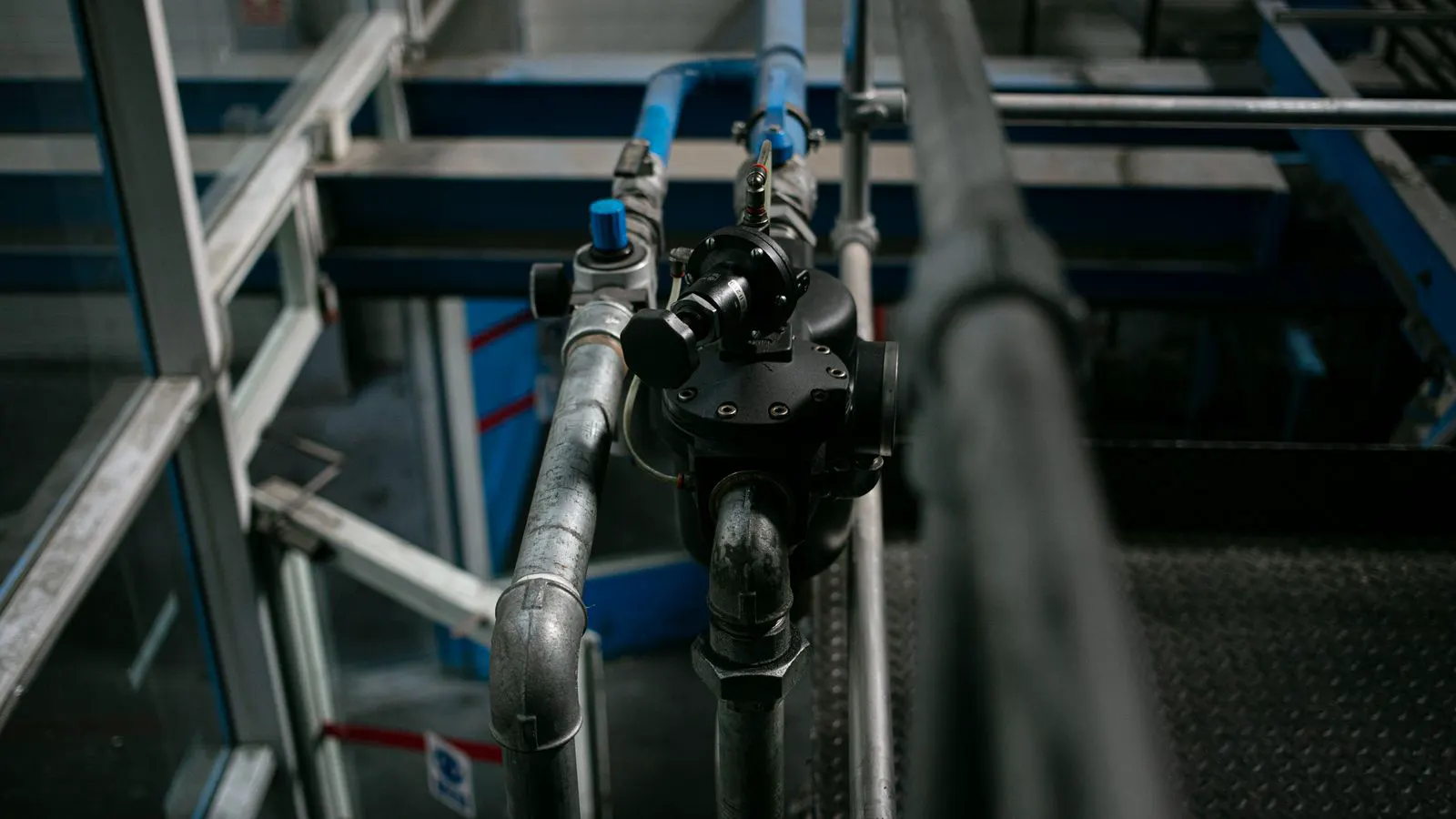
Choose an air preparation unit by evaluating inlet conditions, required output stability, and specific application needs. The correct FRL configuration balances filtration efficiency, regulator response, and lubrication delivery to protect downstream components and ensure reliable pneumatic performance.
- Match the filter element type and micron rating to the specific contaminants in your air supply.
- Select regulator technology based on required flow stability and response speed for your actuator or valve operations.
- Determine if lubrication is needed by checking the materials and seals in your downstream pneumatic components.
- Size the FRL unit to handle peak flow demands, not just average operating conditions.
- Include adequate drain capacity and maintenance access to reduce downtime from water accumulation.
Assess Your Inlet Air Conditions
The first step in selecting an air preparation unit is understanding exactly what you are working with. Do not assume your plant air is clean. Compressed air from a standard rotary screw compressor contains oil mist, water vapor, and particulate matter. The specific composition depends on the compressor type, the presence of an aftercooler, and the length of the piping run.
Before buying anything, run a basic test. Check the inlet pressure at the point of use. Note the temperature fluctuations. If you have a desiccant dryer or a coalescing filter upstream, your FRL unit might need less aggressive treatment. If the air comes directly from the compressor without intermediate treatment, the FRL unit carries the full burden of cleanup.
Engineers often make the mistake of specifying filtration based on the air standard they hope for, rather than the air they actually have. A 5-micron filter element works well for clean shop air. It fails quickly when exposed to heavy oil mist from an unfiltered compressor. The filter element will load up, pressure drop will increase, and the unit will require more frequent servicing.
Document your inlet conditions. This data will drive every subsequent decision in the selection process. If you cannot measure the inlet pressure, start there. You cannot design a regulator around a guess. You cannot size a filter without knowing the contaminant load.
Determine Your Output Requirements
Once you know the inlet, define the output. The air preparation unit must deliver a specific pressure, flow rate, and quality level to your actuators, valves, and cylinders. These requirements vary widely between applications.
A positioning cylinder demands very stable pressure output. It cannot tolerate pressure drops when multiple cylinders operate simultaneously. A standard solenoid valve for a simple push-pull cylinder may need less precise regulation. The difference matters.
Flow requirements are the next constraint. Calculate the maximum simultaneous flow. If you have five cylinders that can actuate at the same time, the FRL unit must deliver the combined flow rate at the regulated pressure. Sizing based on average flow creates a weak point in the system. Under pressure, the unit will starve the actuators, causing slow response and reduced force.
Consider the stability requirement. Some applications need pressure to hold within a tight band. Others can tolerate wider swings. This requirement dictates the regulator technology. A diaphragm regulator offers smooth, stable output. A piston regulator handles higher flow rates but may exhibit more pressure fluctuation under heavy load.
Choose the Correct FRL Configuration
The standard FRL unit consists of three components: filtration, regulation, and lubrication. However, not every application requires all three. This is where many buyers make errors. They purchase a complete FRL unit when a two-stage configuration would be more appropriate.
For applications using all-nylon or all-polymer pneumatic components, lubrication may be unnecessary. These materials often have low-friction properties that reduce seal wear. Adding oil to these lines can attract contaminants, degrade the polymer, and create a sticky mess. In these cases, an FL unit, or a standalone filter and regulator, serves the system better.
Conversely, if your system uses standard nitrile or PTFE seals in metal cylinders, lubrication is standard practice. The oil film reduces friction, extends seal life, and helps maintain valve response. The lubricator must be sized to deliver the correct droplet rate. Too much oil causes waste and potential contamination. Too little oil leads to accelerated seal wear and increased noise in the cylinders.
The filtration stage also has options. A standard coalescing filter removes water and particulates. A desiccant filter provides additional dryness. If your application has strict moisture limits, such as certain food processing or medical pneumatic systems, you may need a higher level of treatment. The FRL unit must be compatible with the upstream treatment provided.
Select the Regulator Technology
Regulator selection is often the most critical part of the FRL configuration. The technology used in the regulator determines the pressure stability and flow characteristics.
Diaphragm regulators are the standard choice for most pneumatic systems. They offer smooth, stable output and are well-suited for precise pressure control. The diaphragm provides a flexible barrier between the inlet and outlet, allowing for fine adjustment. They work well in systems where pressure stability is more important than maximum flow capacity.
Piston regulators handle higher flow rates. The piston mechanism allows for larger bore sizes and faster response. They are better suited for high-demand applications, such as large cylinder arrays or heavy-duty actuator systems. However, piston regulators can exhibit more pressure variation under load. The mechanical action creates some turbulence.
Consider the response speed. If your pneumatic system operates at high frequency, the regulator must respond quickly to pressure changes. A slow-responding regulator will cause lag in pressure output, leading to timing errors in the system. For high-speed applications, select a regulator with a fast-acting mechanism.
Also consider the range of operating pressures. The regulator must handle your inlet pressure range while maintaining the desired outlet pressure. If your inlet pressure fluctuates widely, you need a regulator with a wide working range. A narrow-range regulator will struggle to maintain stable output when the inlet pressure varies.
Evaluate Filtration and Maintenance
The filtration element is a consumable. It will need replacement. The FRL unit you select must make this process easy and cost-effective.
The micron rating determines the particle size the filter will remove. A 5-micron rating is standard for general industrial applications. A 1-micron rating is used for applications requiring finer filtration, such as certain precision pneumatic systems. Do not specify a finer rating than necessary. Finer filters have higher pressure drop and shorter service intervals. They also cost more. Match the rating to your actual contaminant load.
The filter housing must be easy to open for element replacement. Look for a design that allows quick access without draining the entire system. This reduces downtime during maintenance. The drain mechanism is equally important. Water accumulates in the filter bowl. If the drain is not accessible or not reliable, the water will bypass the filter element and enter the regulated air.
Include a drain that is easy to operate. A manual drain cock is standard. An automatic drain valve reduces maintenance frequency but adds cost and complexity. For most applications, a reliable manual drain operated on a regular schedule is sufficient. The key is that the operator knows to drain the unit.
Consider the maintenance interval. A unit that requires element replacement every six months is easier to manage than one that requires it every two weeks. The FRL unit should match your maintenance schedule. If your plant has a strict maintenance program, select a unit with a longer service interval. If your plant has limited maintenance access, select a unit that is easy to service on-site.
Size the Unit for Peak Demand
Sizing the FRL unit is where many selection processes fail. Buyers often size the unit based on the average flow rate. This creates a system that works fine under normal conditions but fails under peak demand.
Calculate the peak flow rate. This is the maximum flow required when all components in the circuit operate simultaneously. This value, not the average flow, should determine the FRL unit size. If the unit cannot deliver the peak flow at the regulated pressure, the system will experience pressure drops. These drops reduce actuator force, slow response times, and can cause components to stall.
Include a safety margin. Select a unit that can handle at least 10 to 15 percent more flow than the calculated peak. This margin accommodates variations in inlet pressure, filter loading, and future system expansion. A unit sized exactly to the peak requirement will struggle as the filter loads and the inlet pressure fluctuates.
The physical size of the unit also matters. A large FRL unit may not fit in the available space. Consider the mounting location. Wall-mounted units save floor space but require a flat surface. Floor-mounted units are heavier and may require additional support. Plan the installation before selecting the unit.
Make the Final Selection
The selection process comes down to matching the unit to your specific requirements. Use the following criteria to evaluate options.
| Criterion | What to look for | Why it matters |
|---|---|---|
| Inlet Contamination | Filter element type and micron rating | Correct filtration removes contaminants before they reach downstream components |
| Flow Capacity | Rated flow rate at regulated pressure | Ensures stable pressure under peak demand conditions |
| Pressure Stability | Regulator technology and response time | Maintains consistent output for precise pneumatic operations |
| Lubrication Need | Lubricator configuration | Protects seals in metal components while avoiding unnecessary oil |
| Maintenance Access | Filter access and drain capability | Reduces downtime and simplifies routine servicing |
| Physical Size | Unit dimensions and mounting options | Fits available space and integrates with existing layout |
The right FRL unit will not be the cheapest option. It will be the option that matches your specific air conditions, flow requirements, and maintenance capabilities. A well-matched unit will provide stable output, protect downstream components, and require predictable maintenance. A poorly matched unit will cause pressure issues, contamination problems, and unnecessary downtime.
Take your inlet data. Define your output needs. Match the FRL configuration to those requirements. The result is a pneumatic system that performs reliably and lasts longer.
Frequently asked questions
Do I always need a lubricator in my FRL unit?
No. Lubricators are primarily needed for systems using standard seals in metal components. If you use all-polymer or all-nylon pneumatic components, lubrication is often unnecessary and can actually cause problems.
How do I know if my FRL unit is the wrong size?
If your actuator response slows down when multiple components operate at the same time, or if your regulated pressure drops below the set point under load, the unit is likely undersized. Pressure instability is the clearest sign of inadequate flow capacity.
What is the difference between a 5-micron and a 1-micron filter?
A 5-micron filter removes particles larger than 5 microns, which is standard for most industrial applications. A 1-micron filter removes smaller particles and is used for applications requiring finer air quality, such as precision systems. Finer filters have higher pressure drop and require more frequent replacement.
Can I use an FRL unit if I have a desiccant dryer upstream?
Yes, but the FRL unit may need a lighter filtration stage. The desiccant dryer removes moisture, but it does not remove all oil mist or particulates. The FRL unit still provides a final stage of treatment, but the filter element may not need to be as aggressive.
How often should I drain the FRL unit?
The frequency depends on your air conditions. In typical industrial environments, daily or weekly draining is common. If you see water in the filter bowl during inspection, increase the drain frequency. Consistent draining prevents water from bypassing the filter element.