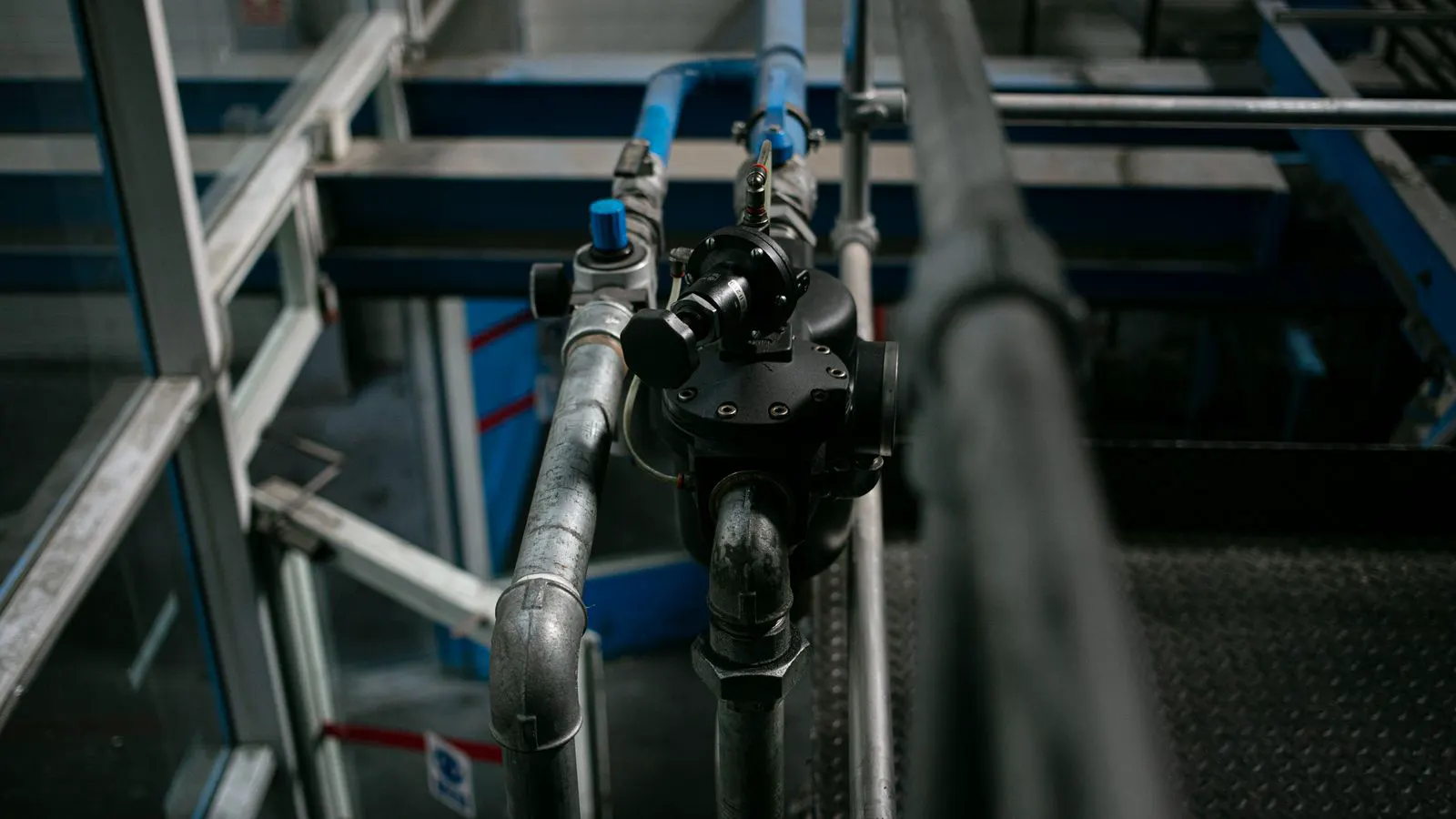
Evaluate pneumatic controllers by checking duty cycle data, solenoid efficiency, and control logic. The right controller lowers energy consumption by matching air delivery to actual work, reducing waste from over-piping or idle flow.
- Measure baseline flow and duty cycle before selecting a new controller to identify actual waste points.
- Prioritize controllers with proportional or modulating valves that reduce over-pressurization at the point of use.
- Use diagnostic features like flow metering and remote monitoring to track savings after installation.
- Match controller response time to the process to avoid unnecessary valve cycling.
Why Controller Choice Drives Energy Performance
Pneumatic energy savings often hide in small, repeated actions. A controller that opens a valve fully for one second when the load needs only three inches of stroke burns air for no reason. The same applies to controllers that hold a cylinder pressurized during a pause between cycles.
When evaluating pneumatic controllers for energy efficient pneumatics, start with the process, not the brand. The controller is the last point of control before air reaches the actuator. If it over-delivers, the compressor works harder than it should. If it cycles too often, wear increases and energy is lost through heat.
Buyers typically focus on cost per unit. That is the wrong starting point. The real cost is the annual energy bill and the maintenance budget. A slightly higher initial investment in a controller with better flow control usually pays for itself through reduced compressor runtime.
What to Measure Before You Buy
You cannot optimize what you do not see. Before comparing controllers, collect three data points from the existing system:
- Average flow rate during active operation.
- Flow rate during standby or idle periods.
- The ratio of active time to total operating time, known as the duty cycle.
These numbers tell you where waste lives. Many plants discover that standby flow accounts for a large share of total consumption. If the existing system keeps valves open or leaks air during idle time, a new controller with proper shutoff logic will show savings immediately.
Use a flow meter for at least one week. Record data by shift. If the process runs intermittently, capture both peak and average values. This baseline also helps you verify savings after installation. Without it, you are guessing whether the change worked or whether the compressor was simply already struggling.
Core Features That Lower Consumption
Not all features improve efficiency. Some add cost without reducing air use. Focus on the capabilities that directly affect how much air reaches the actuator and for how long.
Proportional and Modulating Control
Binary controllers open or close. Proportional controllers open the valve to a specific percentage of flow. For processes that do not require full pressure, this reduces energy use substantially. A robot arm that lifts a light part does not need the same valve opening as one that lifts a heavy part.
Modulating valves offer a similar benefit. They adjust flow continuously rather than in steps. The trade-off is complexity. These controllers require precise tuning. If the process is simple, a well-tuned binary controller with a flow restrictor may be cheaper to maintain.
Duty Cycle Optimization
Many pneumatic systems keep valves energized even when the cylinder is not moving. A controller with dwell timers or position feedback can cut the solenoid current during pauses. This saves energy and reduces coil heating.
Look for controllers that support multiple time settings. A single dwell timer is useful, but processes often have several pause points. A controller that allows you to program individual pauses for each phase of a cycle reduces idle flow more effectively.
Low-Pressure Drop Design
Air loses pressure as it travels through piping and valves. A controller with a low-pressure-drop design maintains usable pressure at the actuator with less input. This means the compressor does not need to work as hard to compensate for losses.
Check the manufacturer’s pressure drop curves. If a controller requires 20 bar input to deliver 16 bar at the port, you are losing energy in the valve itself. A design that maintains 17 bar output from 20 bar input is more efficient, even if the difference seems small.
Remote Monitoring and Diagnostics
Energy efficient pneumatics is not a one-time setting. It is ongoing management. Controllers with digital outputs, flow sensors, or communication ports let you track consumption in real time.
You can monitor for leaks, abnormal duty cycles, or valves that stick partially open. These issues quietly drain energy. Without monitoring, you find them during a breakdown. With monitoring, you fix them before they become major waste.
Criteria Table for Evaluation
Use this table when comparing vendors. It separates features that directly lower energy from features that are nice to have.
| Criterion | What to look for | Why it matters |
|---|---|---|
| Control Type | Proportional or modulating valves | Reduces over-pressurization and matches flow to load |
| Duty Cycle Logic | Adjustable dwell timers and position feedback | Cuts solenoid current during idle periods |
| Pressure Drop | Low delta-P design at rated flow | Reduces compressor load and heat loss |
| Diagnostics | Flow metering and fault logs | Identifies leaks and abnormal consumption early |
| Communication | Modbus, Profinet, or Ethernet | Enables real-time monitoring and data logging |
| Response Time | Fast enough for the process, not slower | Avoids unnecessary cycling and wear |
Common Mistakes in Selection
Buyers make a few recurring errors when choosing pneumatic controllers for energy savings.
First, they buy the cheapest controller that fits the size. The price tag does not reflect operating cost. A basic controller may use 40 percent more air than a proportional one because it cannot modulate flow.
Second, they ignore the compressor side. A controller cannot fix a system with a leaking manifold or oversized piping. If the upstream system is inefficient, the controller will only manage a larger waste stream.
Third, they skip tuning. Even a good controller wastes energy if the set points are wrong. The valve opening percentage, dwell times, and pressure thresholds must match the actual load. A controller that is 90 percent tuned saves less than a basic controller that is 100 percent tuned.
Fourth, they do not verify savings. Without a baseline, you cannot prove that the new controller worked. If the compressor was already running at full capacity, the savings may be hidden. If the process changed after installation, the data will be misleading.
How to Verify Savings After Installation
Verification is the difference between a claim and a result.
- Compare compressor runtime hours before and after installation.
- Track power consumption at the compressor using a meter.
- Measure flow at the controller output using a calibrated meter.
- Calculate the energy difference over a fixed period, such as one week.
Do not rely on a single day of data. Production patterns change. Run the comparison across at least two full production cycles. If the savings are real, they will appear consistently.
If you see no savings, check the tuning first. Look for valves that stick, set points that are too high, or dwell times that are too long. The controller may be working correctly, but the parameters may not match the process.
Decision Checklist
Use this checklist when you are ready to make a purchase decision.
- Baseline flow and duty cycle data collected for at least one week
- Baseline compressor power consumption recorded
- Controller control type matches process needs (binary, proportional, or modulating)
- Pressure drop data reviewed against available system pressure
- Diagnostics included for flow monitoring and fault logging
- Communication protocol compatible with existing plant systems
- Tuning time budgeted and documented
- Verification plan set with a fixed measurement period
The right controller is not the one with the most features. It is the one that matches your process, reduces waste at the point of use, and gives you the data to prove the savings. Start with measurement. Then choose the control logic that fits the data. Finally, verify the result. That sequence keeps energy efficient pneumatics from being a guess.
Frequently asked questions
Do I need a proportional controller to save energy?
Not always. If your process uses full pressure for most of the cycle, a well-tuned binary controller with proper shutoff may be sufficient. Proportional control helps most when the load varies or when the process requires partial pressure.
How long does it take to see savings?
Savings appear immediately after installation if the baseline is accurate. You need a measurement period of at least one week to confirm the change is consistent and not due to production fluctuations.
Can I upgrade my existing controller without changing piping?
In many cases, yes. Most controllers mount to the same manifold or valve block. Check the port size, electrical requirements, and communication protocol before ordering.
What is the biggest source of waste in pneumatic systems?
Standby flow and leaks are the top two. Controllers with proper shutoff logic reduce standby flow. Leaks require separate repair, but monitoring features help you find them faster.
How do I know if my compressor is the problem?
If the compressor runs constantly even when the system is idle, the problem is likely upstream. Check for leaks, oversized piping, or a compressor that is too large for the system before replacing the controller.