Select the correct pressure regulator by matching type, capacity, and control method to process demand. Evaluate stability, noise, and maintenance needs before purchase to ensure reliable pneumatic components in your system.
- Match regulator type to the specific duty: diaphragm for general use, pilot-operated for high capacity, and servo for tight control.
- Size the regulator for the maximum required flow, not the average, to prevent pressure drop under peak load.
- Verify the input pressure range and set the outlet pressure with a clear safety margin.
- Choose materials and fittings that match the medium and ambient conditions to avoid corrosion or seal failure.
- Include a pressure gauge and an inline filter to protect the regulator from particulates and moisture.
What regulator type fits the process load?
The first decision in pneumatic components selection is the regulator type. The wrong choice causes pressure hunting, slow response, or premature seal wear. The three main classes are diaphragm, pilot-operated, and servo-controlled regulators. Each serves a different duty.
Diaphragm regulators are the standard for most low to medium flow applications. They use a spring and a diaphragm to balance input pressure against set output pressure. They are compact, low cost, and easy to maintain. They work well for small actuators, pneumatic tools, and control circuits where flow demand is modest and stable. A typical diaphragm regulator on a single cylinder line or a small pneumatic nailer holds steady pressure because the flow demand is predictable. If the demand changes rapidly, however, the spring-loaded diaphragm may not react fast enough. This results in pressure lag, which slows the actuator stroke and reduces cycle efficiency. For these reasons, diaphragm units are best suited to applications where the maximum flow demand is low and the pressure set point rarely changes during operation.
Pilot-operated regulators use the regulator output to control a larger valve. They handle much higher flow than diaphragm units and maintain output pressure more steadily under load. They are the right choice for large cylinders, long pipe runs, or multiple actuators on the same circuit. In a pilot-operated design, the pilot valve moves a spool that opens the main supply port. This allows the regulator to pass significantly more air than a simple diaphragm unit. This makes pilot-operated regulators the standard choice for hydraulic-like pneumatic circuits with high flow requirements. They are also more stable when the output pressure needs to be held against a fluctuating load.
Servo-controlled regulators use electronic feedback to hold set pressure with very tight tolerance. They respond in milliseconds and can modulate pressure precisely. They are used in automated cells where position or force control depends on stable pneumatic pressure. They cost more and require power and calibration. A servo regulator typically includes an electronic controller, a pressure sensor, and a position-controlled valve. This combination allows the unit to adjust its opening in real time based on the measured output pressure. This level of control is necessary in applications such as precision material handling, where the force applied by a gripper must remain constant despite changes in part size or position. The added complexity means these units require a stable power supply and periodic calibration to maintain accuracy.
How do you size the regulator for the required flow?
Regulators are rated by maximum flow at a given pressure drop. Sizing for average flow is a common mistake. Size for the peak demand of the system.
Determine the total flow required by summing the flow of all actuators, valves, and tools that operate simultaneously or in quick succession. Add a margin for leaks and fittings. If the regulator cannot pass that flow, output pressure will collapse when demand spikes. This causes slow actuator strokes and inconsistent cycle times.
Start with the data sheet for each actuator and valve. Look for the maximum flow rate at the specific pressure set point. Sum these values for all components that operate in the same cycle. Do not assume that the average flow equals the peak flow. In many systems, multiple actuators fire in quick succession, creating a short burst of high demand. This burst is what the regulator must handle.
Check the manufacturer’s flow curve for the specific model. Flow capacity changes with inlet pressure, outlet pressure, and temperature. A regulator rated for a certain flow at 6 bar inlet and 4 bar outlet may deliver far less at 8 bar inlet and 6 bar outlet. Use the curve, not the nameplate flow number.
For pilot-operated units, the capacity is usually stated in cubic metres per minute at a standard pressure drop. For servo units, capacity may be limited by the valve stroke and control loop. Confirm the rated flow covers your peak case with a 15 to 20 percent margin.
Consider the pressure drop across the regulator. The flow capacity is highest when the pressure drop is large. As the outlet pressure approaches the inlet pressure, the available flow decreases. If your application requires a small pressure drop, check the flow curve carefully. A regulator may be rated for 100 m3/min at a 4 bar drop, but deliver only 40 m3/min at a 1 bar drop. This difference can be the difference between a smooth stroke and a slow, hesitant movement.
What control method matches the set pressure accuracy?
The control method determines how well the regulator holds set pressure under varying load and input conditions. Manual regulators use a screw or knob to set spring tension. They are simple and reliable but drift with temperature and wear. They are adequate for fixed pressure applications where a small variation is acceptable.
Manual control is the most common method in general pneumatic systems. The user turns a knob to set the pressure, which compresses a spring. This spring pushes against the diaphragm. The simplicity of this design makes it reliable and easy to service. However, the accuracy depends on the friction of the adjustment mechanism and the elasticity of the spring. Over time, the spring can lose tension or the mechanism can wear, causing the set pressure to drift. This drift is usually small but can be significant in applications where pressure stability is critical.
Semi-automatic regulators use a pressure switch or sensor to adjust the set point. They can compensate for input pressure changes and hold output within a tighter band. They are useful when the supply pressure fluctuates from the compressor or when multiple regulators share a header.
Semi-automatic units use a pressure switch to detect deviations in the output pressure. When the pressure drops below the set point, the switch opens a valve to increase flow. When the pressure rises above the set point, the switch closes the valve. This method provides better stability than manual control but is slower than electronic control. It is well suited to applications where the supply pressure varies, such as systems fed by a single compressor with multiple consumers. In these cases, the pressure at the compressor outlet can fluctuate as other consumers start and stop. A semi-automatic regulator can compensate for these fluctuations and maintain a more stable output.
Fully automatic or servo regulators use an electronic controller and a position valve. They maintain set pressure to a tight tolerance and can change set point digitally. They are required for processes where pressure stability directly affects product quality or actuator positioning. They need a stable power supply and periodic calibration.
The set pressure accuracy you need depends on the application. A pneumatic tool may work fine with a 0.2 bar variation. A precision gripper or dosing valve may not. Define the allowable band before selecting the unit.
For most general industrial applications, a variation of 0.1 to 0.2 bar is acceptable. For precision applications, such as medical dosing or delicate material handling, the allowable variation may be as low as 0.01 bar. This requirement determines the type of regulator needed. A manual regulator is sufficient for general use, but a servo regulator is required for precision tasks.
Which materials and fittings match the service conditions?
Material selection prevents corrosion, seal degradation, and contamination. The regulator body, diaphragm, seals, and fittings all interact with the medium and the environment.
For dry, clean compressed air, anodized aluminum bodies and nitrile or PTFE seals are common. For humid or oily air, stainless steel bodies and PTFE or FKM seals perform better. For corrosive air, such as air with traces of chlorine or acid vapors, use stainless steel or coated bodies.
The choice of materials depends on the air quality and the environmental conditions. In a clean, dry environment, aluminum is a good choice because it is lightweight and inexpensive. However, aluminum is susceptible to corrosion in the presence of moisture or corrosive substances. In such cases, stainless steel or coated bodies are more appropriate.
The seals are critical components. They must be compatible with the air quality. Nitrile seals are common in general applications, but they can degrade in the presence of oil. PTFE seals are resistant to many chemicals and are suitable for corrosive environments. FKM seals are resistant to oil and heat, making them suitable for oily air applications.
The inlet and outlet fittings must match the pipe thread or flange type. Use standard fittings and torque values. Over-tightening can crack aluminum bodies or strip threads. Under-tightening causes leaks at the regulator body.
Use the correct thread size and pitch. Mismatched threads can cause leaks or damage the regulator. Use thread sealant or PTFE tape as specified by the manufacturer. Do not over-tighten the fittings. Aluminum bodies can crack if tightened too much, and stainless steel threads can strip if the torque is too high.
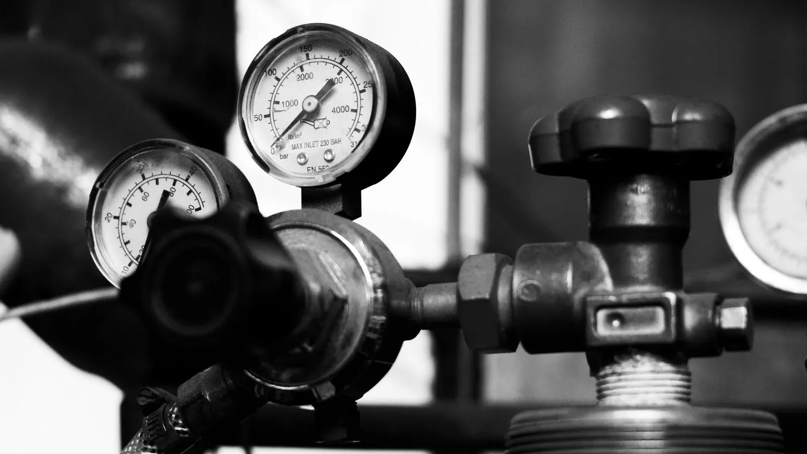
Choose a regulator with a pressure gauge port or an inline gauge. A gauge helps you verify set pressure and detect drift. It also helps when diagnosing intermittent failures. A gauge with a broken tube or frozen mechanism can mislead maintenance work.
A pressure gauge is essential for verifying the set pressure. It also helps in diagnosing problems. If the gauge shows a pressure different from the expected value, it indicates a problem with the regulator or the supply. A gauge with a broken tube or frozen mechanism can give false readings, leading to incorrect adjustments.
What protection and installation details are required?
A regulator is only as good as the air it receives and the protection it has. Install the regulator after a filter and after a moisture separator. Particulates and liquid water damage diaphragms and seals. A 5 micron or finer filter is a standard practice for most pneumatic circuits.
The quality of the air supply is critical. Compressed air from a compressor contains water, oil, and particulates. These contaminants can damage the regulator components. A filter removes the particulates, and a moisture separator removes the water. Without these protections, the diaphragm and seals will wear prematurely.
Mount the regulator in an accessible location. The set point adjustment must be reachable without removing the unit. Leave space for a wrench and a gauge. Avoid mounting it where it will be exposed to vibration, heat, or physical impact. A regulator under a machine guard is hard to service and tends to accumulate dust.
The installation location affects the performance and lifespan of the regulator. It should be easy to access for adjustment and maintenance. It should be protected from vibration, heat, and physical impact. A regulator mounted in a location with high vibration can suffer from mechanical wear. A regulator mounted near a heat source can suffer from thermal degradation of the seals.
Use a pressure gauge to verify the set pressure after installation. Set the regulator, then apply load and check the drop. If the output drops more than expected, the unit is undersized or the filter is clogged. Adjust the set point slightly higher to compensate for load drop, but do not exceed the maximum rated outlet pressure.
After installation, verify the set pressure with a gauge. Apply the load and check the pressure drop. If the pressure drop is excessive, the regulator may be undersized or the filter may be clogged. Adjust the set point to compensate for the load drop, but do not exceed the maximum rated outlet pressure.
How do you verify performance after installation?
After installation, run the system under full load for a defined period. Record the output pressure at the regulator outlet and at the actuator. Compare the two. A significant pressure drop between the regulator and the actuator indicates a restriction in the line or a regulator that is not sized correctly.
Run the system under full load for a defined period. Record the output pressure at the regulator outlet and at the actuator. Compare the two. A significant pressure drop between the regulator and the actuator indicates a restriction in the line or a regulator that is not sized correctly.
Check for leaks at the regulator body and fittings. Use a leak detection method appropriate to the pressure level. A small leak at a regulator body can cause pressure instability and short-cycle failure.
Use a leak detection method appropriate to the pressure level. Soap solution is a common method for low-pressure systems. For higher pressures, use an electronic leak detector or an ultrasonic detector. A small leak at the regulator body can cause pressure instability and short-cycle failure.
Monitor the regulator for temperature rise. Excessive heat indicates high flow, poor cooling, or a regulator operating near its limit. If the body is hot to the touch during normal operation, the unit may be undersized.
Monitor the regulator for temperature rise. Excessive heat indicates high flow, poor cooling, or a regulator operating near its limit. If the body is hot to the touch during normal operation, the unit may be undersized.
Keep a maintenance log. Record the date of installation, the set pressure, the measured pressure under load, and any adjustments. This record helps when diagnosing intermittent failures and supports predictive maintenance programs.
Keep a maintenance log. Record the date of installation, the set pressure, the measured pressure under load, and any adjustments. This record helps when diagnosing intermittent failures and supports predictive maintenance programs.
What common mistakes cause regulator failure?
The most common mistake is sizing the regulator for average flow instead of peak flow. The second is ignoring the inlet pressure range. A regulator set for 6 bar inlet will behave differently at 8 bar. The third is using a regulator without a filter upstream. Water and dust destroy seals faster than normal wear.
The most common mistake is sizing the regulator for average flow instead of peak flow. The second is ignoring the inlet pressure range. A regulator set for 6 bar inlet will behave differently at 8 bar. The third is using a regulator without a filter upstream. Water and dust destroy seals faster than normal wear.
Another mistake is mounting the regulator in a location where it cannot be adjusted or inspected. A regulator hidden in a panel or behind a guard is a maintenance problem waiting to happen.
Another mistake is mounting the regulator in a location where it cannot be adjusted or inspected. A regulator hidden in a panel or behind a guard is a maintenance problem waiting to happen.
Do not use a regulator as a flow control valve. Regulators control pressure, not flow. If you need to limit flow, use a separate flow control valve. Using a regulator to throttle flow causes hunting and accelerates wear.
Do not use a regulator as a flow control valve. Regulators control pressure, not flow. If you need to limit flow, use a separate flow control valve. Using a regulator to throttle flow causes hunting and accelerates wear.
Frequently asked questions
What is the difference between a diaphragm regulator and a pilot-operated regulator?
A diaphragm regulator uses a spring and diaphragm to balance pressure and suits low to medium flow. A pilot-operated regulator uses the output to control a larger valve and handles higher flow and larger circuits.
How do I know if my regulator is undersized?
If output pressure drops significantly when the system reaches peak load, the regulator is likely undersized. Check the flow curve and compare the measured flow to the rated flow at your actual inlet and outlet pressures.
What inlet pressure range should I choose?
Choose a regulator whose rated inlet range covers your actual supply pressure with margin. If your supply pressure varies, select a unit rated for the full range or use a semi-automatic regulator that compensates for inlet changes.
Do I need a filter before the regulator?
Yes. Install a filter and moisture separator upstream of the regulator. Particulates and liquid water damage diaphragms and seals and cause pressure instability.
How often should I check the regulator set pressure?
Check the set pressure after installation and after any maintenance. Monitor the output pressure under load during routine inspections. Record the values in a maintenance log to detect drift early.