Air pressure requirements determine actuator force, speed, and response. Most systems use standard supply pressures, but the specific range must match the application. Choosing the wrong pressure leads to oversized parts or insufficient performance. This guide explains how supply pressure affects sourcing and component performance.
- Supply pressure sets the maximum force an actuator can deliver.
- Lower pressure systems use larger bores but smaller fittings.
- Higher pressure allows smaller components but demands tighter seals.
- Always match the actuator pressure rating to the system supply.
- Check actuator pressure settings before finalizing the selection.
Why Supply Pressure Changes Actuator Sizing
Pneumatic actuators convert compressed air into linear or rotary motion. The air pressure requirements of the system define how much force the actuator can generate and how fast it can move. A designer sets the supply pressure first. That decision drives the bore size, the rod diameter, and the fitting size. If the supply pressure is low, the actuator must have a larger bore to produce the same force. If the supply pressure is high, a smaller bore is enough.
The standard pressure ranges in industrial automation fall into two broad groups. Low pressure systems typically run between 30 and 60 psi. High pressure systems operate between 60 and 120 psi. Most general purpose installations fall in the middle, around 70 to 90 psi. The exact number depends on the compressor, the filter, the regulator, and the distance of the air line.
A buyer must know the pressure at the point of use, not just at the compressor. Friction in the piping drops the pressure. A long run of small diameter tubing can eat up several psi before the air reaches the cylinder. This loss changes the effective air pressure requirements for the actuator. The sizing calculation must use the pressure at the actuator inlet, not the compressor output.
How Pressure Affects Force and Stroke
The force from a single acting or double acting cylinder comes from the product of pressure and area. The formula is simple. Force equals pressure times the piston area. If the pressure is 90 psi and the piston area is 3 square inches, the force is 270 pounds. If the pressure drops to 60 psi, that same cylinder only produces 180 pounds.
This relationship directly impacts sourcing decisions. An engineer needs 200 pounds of force. At 90 psi, a small bore cylinder works. At 60 psi, the bore must be bigger. The bigger bore means a larger part, a longer body, and larger fittings. It also changes the weight and the installation space. The actuator pressure settings must match the available supply. If the supply is low, the designer cannot rely on a high pressure part to do the work.
Stroke length is independent of pressure in most cases. A cylinder can have a 1 inch stroke or a 12 inch stroke. Pressure does not change the distance the rod travels. However, pressure affects the speed. A higher pressure drives the rod faster. For the same bore and the same orifice, a cylinder at 100 psi moves faster than one at 60 psi. The speed is also limited by the flow capacity of the air supply. A small regulator will not feed a large cylinder at high speed, no matter how much pressure is present.
Standard Pressure Ranges and Component Ratings
Most pneumatic components carry a rated maximum pressure. This rating is a safety limit, not a recommended operating point. A cylinder marked 150 psi can handle that pressure without failing. But running it at 150 psi all the time is bad practice. The seals wear faster. The piston ring wear is higher. The risk of a burst increases if the pressure spikes.
The operating pressure should be lower than the rated maximum. A common rule is to keep the working pressure below 80 percent of the rating. This gives a buffer for surges and pressure fluctuations. A component rated for 125 psi should ideally run at 90 psi or less. The actuator pressure settings should reflect this buffer. The regulator is set to the working pressure, and the component rating is chosen to be higher than that set point.
The table below shows how typical pressure ranges affect common actuator features.
| Pressure Range | Bore Size Trend | Fitting Size | Seal Material | Response Time |
|---|---|---|---|---|
| 30 to 60 psi | Larger bores needed | Standard | Standard FKM | Slower |
| 60 to 90 psi | Moderate bores | Standard | Standard FKM | Standard |
| 90 to 120 psi | Smaller bores | Standard or reduced | High temp FKM | Faster |
| Above 120 psi | Reduced bores | Specialized | Specialized | Very fast |
Impact on Seals and Materials
Seal materials are sensitive to pressure. Low pressure systems use standard FKM or NBR seals. These materials are cheap and easy to replace. High pressure systems often require harder seal compounds. The seal must resist extrusion, which is the force that pushes the seal past the piston or rod. At high pressure, the seal face sees a high radial load. If the material is too soft, it deforms and leaks.
The rod finish also matters. At low pressure, a standard chrome rod is fine. At high pressure, the rod may need a harder surface treatment. The pressure pushes the rod against the seal, and any surface roughness will cut the seal. A rough rod at 120 psi will fail quickly. A smooth, hardened rod lasts much longer. The air pressure requirements dictate the rod specification. A buyer should not assume a standard rod will work at high pressure.
The housing material changes too. Low pressure cylinders use aluminum or steel. High pressure cylinders may need thicker walls or special steel. The pressure creates tensile stress in the wall. If the wall is too thin, it will bulge or rupture. The component data sheet lists the maximum allowable pressure for the specific wall thickness. The sizing guide must account for this. A high pressure application requires a heavier part.
Worked Example in Plain Words
Consider a machine that needs to push a gate open. The gate weighs 300 pounds and has friction that adds another 50 pounds. The total load is 350 pounds. The designer has a compressor that supplies 90 psi at the regulator. The effective pressure at the actuator is 85 psi after line losses.
The designer calculates the required area. 350 pounds divided by 85 psi is about 4.1 square inches. A standard cylinder with a 2 inch bore has an area of about 3.14 square inches. That is too small. It would only produce 266 pounds of force. The 2 inch bore is out. The designer picks a 2.5 inch bore. That area is about 4.9 square inches. At 85 psi, that gives 416 pounds of force. That is enough.
Now consider a different plant. The compressor is older and only provides 60 psi at the regulator. The effective pressure is 55 psi. The 2.5 inch bore now produces 269 pounds of force. That is not enough for the 350 pound load. The designer must go to a 3 inch bore. That area is 7.07 square inches. At 55 psi, that gives 388 pounds of force. The 3 inch bore is the correct choice.
The same gate, same load, different pressure. The actuator size changes completely. This is why the air pressure requirements must be verified before ordering. A part that works in one plant will fail in another if the supply pressure is different. The actuator pressure settings on the regulator must match the design pressure used in the calculation.
Common Mistakes in Selection
Buyers often make the same errors. The first is using the compressor pressure instead of the actuator pressure. The compressor may say 100 psi, but the line loss and regulator drop it to 80 psi. The designer uses 100 psi in the math. The cylinder is too small. It does not reach full stroke. The gate sticks. The engineer blames the cylinder, but the pressure is the real issue.
The second mistake is ignoring the pressure rating. A cylinder rated for 150 psi is selected for a 90 psi system. This seems safe, but it is wrong. The seals are overbuilt. They are harder and stiffer. They do not seal as well at low pressure. They cost more. A cylinder rated for 90 psi is better. It uses softer seals that match the pressure. The part is lighter and cheaper. The rating should be close to the working pressure, not double it.
The third mistake is not checking the regulator capacity. The regulator is set to 90 psi, but it only passes 10 cubic feet per minute. The cylinder needs 20 cubic feet per minute to move at the required speed. The pressure drops when the cylinder extends. The actuator stalls. The regulator is the bottleneck. The air pressure requirements include flow, not just static pressure. A small regulator cannot feed a large actuator at speed.
How to Verify Pressure at the Point of Use
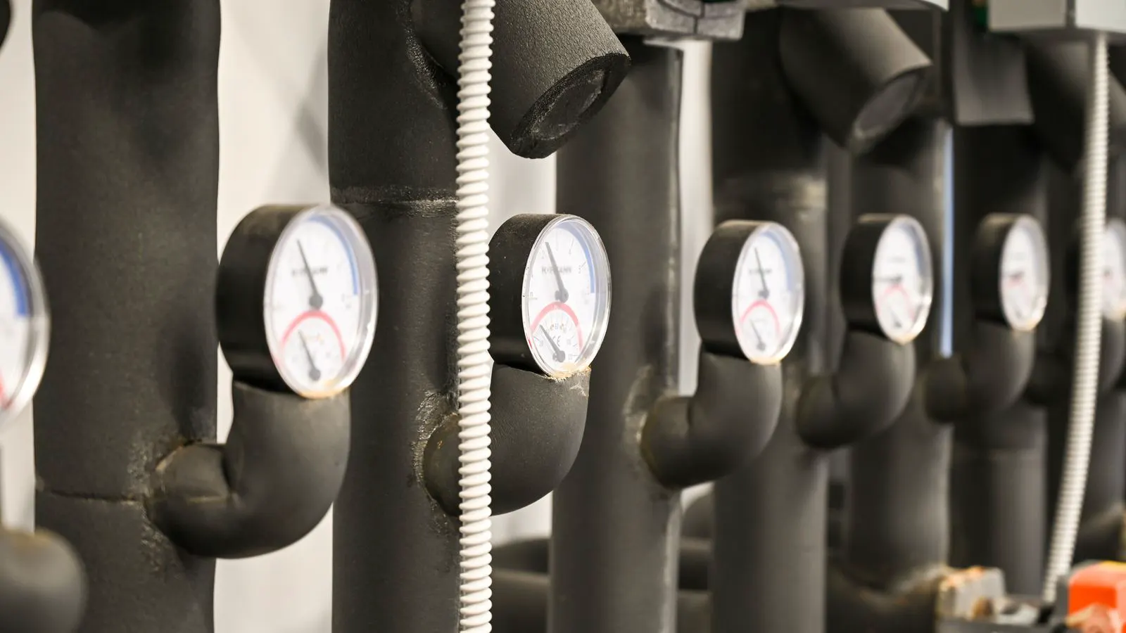
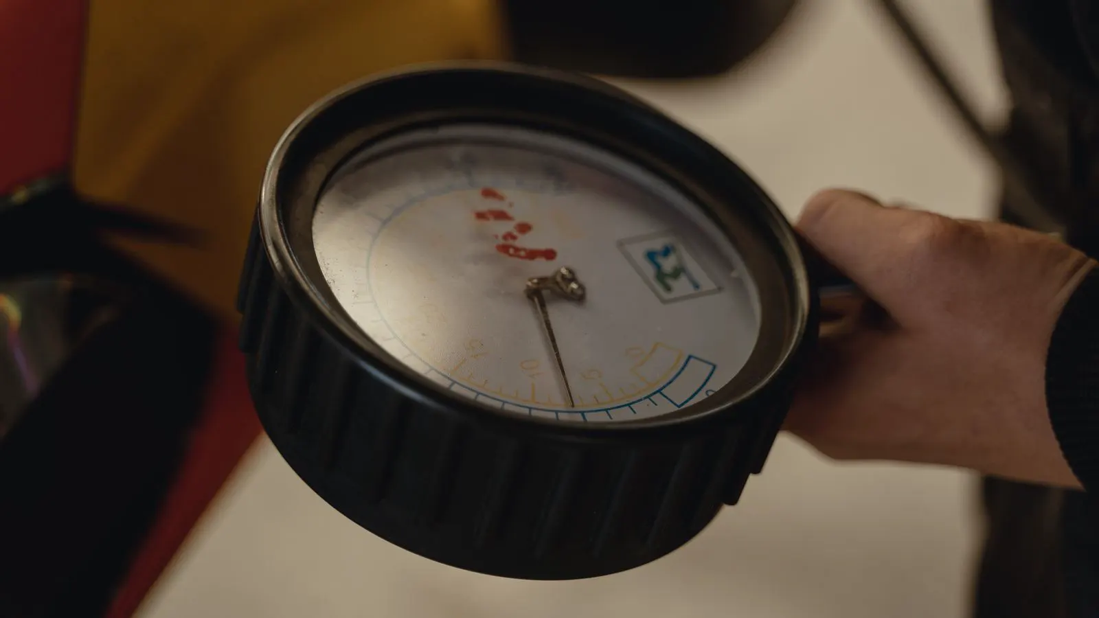
Verification is a physical check. Install a gauge at the actuator inlet. Run the system. Watch the gauge when the actuator extends. The pressure will drop as the air flows into the cylinder. This drop is the line loss plus the flow demand. The designer uses this observed number for the sizing. A gauge at the compressor is useless for sizing. It does not tell you what the actuator sees.
The check must be done with the line at full length. A short test line gives a higher pressure. A long line gives a lower pressure. The test must match the real installation. If the line is 50 feet of 1/4 inch tubing, the test must use the same. The pressure drop is a function of length and diameter. A short test underestimates the loss. The actuator will be undersized.
The verification step is part of the sourcing decision. It confirms the effective pressure. It tells the buyer if the regulator is big enough. It tells the buyer if the line size is correct. Without this check, the sizing is a guess. The actuator pressure settings are set to the observed number. The component is chosen to match that number. The system works because the pressure was measured, not assumed.
Final Checks Before Ordering
Before placing the order, run a final review. Check the working pressure. Check the required force. Check the required speed. Check the stroke length. Match these to the component data sheet. The data sheet lists the force at a specific pressure. If the data sheet says 500 pounds at 100 psi, and your pressure is 85 psi, the force is lower. Recalculate. Do not rely on the table value. Scale it to your pressure.
Check the seal material. Check the rod finish. Check the fitting size. These details are driven by the pressure. A high pressure application needs different seals and rods. A low pressure application can use standard parts. The air pressure requirements are not just a single number. They are a set of conditions that define the whole component. The buyer must respect all of them.
The final step is to confirm the regulator setting. The regulator is set to the working pressure. The component rating is higher. The system has a buffer. The actuator operates within its safe range. The force is sufficient. The speed is correct. The part is the right size. The selection is complete.
Frequently asked questions
What is the standard pressure for pneumatic actuators?
Most industrial systems run between 60 and 120 psi. General purpose applications often use 70 to 90 psi. The exact pressure depends on the compressor and line losses.
How does pressure affect the force of a cylinder?
Force equals pressure times piston area. Higher pressure gives more force from the same bore. Lower pressure requires a larger bore to produce the same force.
Can I use a high pressure rated cylinder in a low pressure system?
Yes, but it is not ideal. High pressure cylinders have harder seals that do not seal as well at low pressure. They are also heavier and more expensive.
Do I need to check pressure at the actuator?
Yes. The pressure at the actuator is lower than at the compressor due to line loss. The sizing calculation must use the pressure at the actuator inlet.
What if the pressure drops when the cylinder extends?
This is normal. The pressure drop depends on the flow demand and the line size. If the drop is too high, the regulator or line must be enlarged.