Measure compressed air consumption with flow meters and pressure gauges, then lower usage by fixing leaks, right-sizing components, and controlling demand. This guide walks through baseline setup, inspection, and verification steps to improve energy efficiency.
- Baseline measurement gives a reference point for tracking savings over time.
- Leaks are the most common source of waste in most industrial air systems.
- Right-sizing valves and actuators prevents over-pressurizing and over-delivery.
- Regular verification confirms that efficiency gains hold after changes.
Why a Baseline Matters Before Any Changes
Compressed air systems rarely behave the same way every month. Demand shifts with production schedules, maintenance work, and seasonal changes in ambient temperature. Without a recorded baseline, you cannot tell whether a drop in usage comes from real efficiency gains or from a temporary reduction in output.
A baseline is a documented snapshot of current consumption. It includes average flow rate, supply pressure, and duration of high-use periods. You do not need a complex data logger to start. A portable flow meter and a pressure gauge can capture enough detail for an initial assessment.
The goal is not perfection. The goal is a defensible reference point. When you later install a new controller or repair a leak, you compare the new reading against the old one. This comparison is what makes the improvement measurable.
Step 1: Map the Air Distribution Path
Start at the compressor discharge and follow the pipe to the point of use. Mark every branch, tee, and junction. Note where valves, regulators, and actuators connect. A simple sketch with labels helps. You do not need architectural precision. You need a map that shows where air leaves the main line and where it returns.
This step matters because air can be consumed at many points. A single actuator may draw a small amount continuously. A large cylinder may draw a burst during a cycle. A leak at a junction may be invisible until the line pressure drops. Knowing the layout lets you isolate sections for testing.
If the system is large, divide it into zones. Group nearby points of use into one zone. This makes later measurement easier. You can test one zone at a time and record the result separately.
Step 2: Record Supply Pressure and Flow
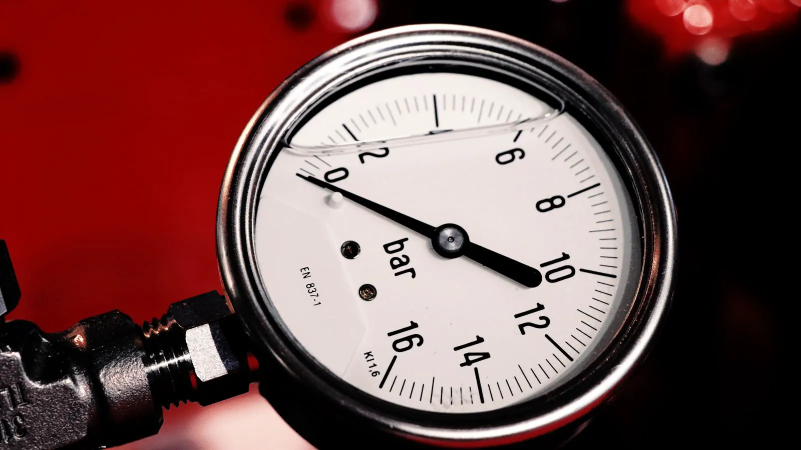
Install a pressure gauge at the compressor discharge and at the nearest point of use. Record the readings during normal operation. Then attach a portable flow meter to a representative section of the main line. Run the system for a full work cycle. Note the peak flow and the average flow over that period.
If the flow meter is not available, use a pressure drop method. Measure pressure at two points along a straight pipe section of known diameter. The drop indicates flow, but the relationship depends on pipe size and friction. This method gives an estimate, not a precise value. Use it for comparison, not for billing.
Record the data in a simple table. Date, time, pressure, flow, and operating condition. A spreadsheet works fine. The point is to create a repeatable record. If you measure the same day next month under the same conditions, you can see the change.
Step 3: Inspect for Leaks and Waste
Walk the pipe layout with a listening device or a soap solution. Listen for hissing at fittings, couplings, and valve stems. Apply soap solution to suspected joints. Bubbles indicate a leak. Most leaks are small, but they add up quickly over a full shift.
Check for air blowing through open valves. A pilot-operated valve left cracked open will waste air continuously. A solenoid valve with a stuck or worn diaphragm may leak through the body. These are common failures in high-cycle applications.
Look for air venting through unneeded openings. A pressure gauge with a loose connection may hiss. A drain valve left open after a maintenance purge may vent air to atmosphere. A filter housing with a cracked housing may leak around the seal.
Log each leak found. Note the location, estimated size, and the component involved. This log becomes your repair list. Prioritize leaks that are easy to fix first. A loose fitting can be tightened in minutes. A worn valve may need a kit replacement or a full valve swap.
Step 4: Check Pressure Regulation and Demand Control
Review the pressure settings at each regulator. Many systems run at a pressure higher than the point of use needs. If a cylinder requires 6 bar to operate, but the regulator is set at 10 bar, the system wastes energy in the compressor and in the piping.
Compare the set pressure to the minimum required pressure for the application. Lower the regulator to the lowest pressure that still performs the task. Test the equipment after the change. If the cycle time or force changes, adjust accordingly.
Check for pressure drops across the line. A long run of undersized pipe can cause a significant drop by the time air reaches the far end. Operators may compensate by raising the compressor set pressure, which wastes energy. If the drop is excessive, consider upsizing the main line or adding a booster.
Demand control is the next layer. Some applications only need air intermittently. A motorized valve or a relay can cut supply when the device is idle. This prevents continuous flow through a component that does not need it. The saving depends on how often the device is active and how much flow it draws when inactive.
Step 5: Right-Size Components and Controls
Review the actuators, valves, and cylinders in the system. If a cylinder is significantly larger than needed for the load, it will consume more air per stroke. It will also require higher pressure if the bore area is excessive. A smaller cylinder often provides the same force with less air.
Valves are a major source of waste if they are oversized. A large flow valve left partially open wastes air because the pressure drop across it is not controlled efficiently. A valve sized close to the required flow, with the correct porting, reduces the pressure loss and the air drawn from the line.
Controllers and timers matter too. If a device cycles faster than the process requires, it consumes air on a shorter interval. Adjusting the cycle time, if the process allows, can lower average flow. If the process requires a fast cycle, then the control strategy must match it. A poorly tuned controller can cause short cycles and higher average demand.
When replacing components, specify the required flow and pressure, not just the model number. Ask the supplier for the flow curve and the pressure drop data. Use that data to confirm the new part will not over-deliver. Over-delivery is waste.
Step 6: Implement a Monitoring Routine
After the initial measurement and repair work, set up a recurring monitoring routine. Check the pressure gauges once a week. Run the flow meter during a standard production cycle once a month. Compare the readings to the baseline.
Track the data in a simple log. Record the date, the measured flow, the measured pressure, and any changes made that week. A trend line helps. A gradual upward trend may indicate a developing leak or a failing component. A sudden drop after a repair confirms the fix.
Assign responsibility for the checks. A single person who owns the routine is more likely to keep it consistent than a team that shares the task. The person should have access to the tools and the authority to stop work if a leak is found.
Step 7: Verify the Savings and Document the Change
Once a change is made, verify the result. Re-run the same test used for the baseline. Measure flow and pressure under the same operating conditions. Record the new values. Calculate the difference.
Do not rely on a single reading. Run the test at least two or three times over a short period. Average the results. This reduces the effect of random variation. If the average flow is lower than the baseline, the change is effective.
Document the change. Note what was replaced, what was adjusted, and the date. Include the before and after readings. This record supports future decisions. If a similar system is being built elsewhere, the data can be reused.
If the savings are small, do not discard the change. Small savings add up over a full year. A leak that wastes a small amount of air continuously can represent a significant cost over 12 months. The total matters.
Common Mistakes That Block Progress
The most common mistake is measuring only the compressor. The compressor tells you the total energy input, but it does not tell you where the air is going. A compressor may run longer because a leak is downstream. Fixing the leak may not change the compressor runtime immediately if the control system is not sensitive enough. Measure at the point of use.
Another mistake is assuming that lower pressure is always better. Some applications need a minimum pressure to generate the required force. Dropping the pressure below that minimum will not save air. It will simply stop the machine. Test the application before changing the set point.
A third mistake is fixing one leak and stopping. Systems degrade over time. Fittings loosen. Seals wear. A leak repaired today may reappear in a few weeks. A routine inspection catches the next leak before it becomes a large waste source.
A fourth mistake is ignoring the control logic. A valve may be correctly sized, but the timer may be set to cycle too often. The air is wasted not because of the hardware, but because of the program. Review the control settings as carefully as the hardware.
Verification and Ongoing Management
Verification is not a one-time event. It is a habit. The baseline you created at the start is your anchor. Every month, you compare the current reading against that anchor. If the reading drifts upward, investigate. If it drops, investigate the change that caused it.
Keep the log accessible. A paper notebook works if it is kept in a fixed location. A spreadsheet works if it is saved in a shared folder. The format matters less than the consistency. A consistent log is a tool for decision making.
The long-term goal is not to reduce air consumption to zero. The goal is to match air delivery to actual demand. Every liter of air drawn from the compressor that is not needed by the process is energy that was generated and lost. Reducing that waste is the core of energy efficiency in a pneumatic system.
When the system is well maintained, the savings are durable. The components still work. The pressure is stable. The cycle times are correct. The only change is that less air is wasted. That is the definition of a healthy pneumatic system.
Frequently asked questions
How often should I measure compressed air consumption?
Measure at least once a month during normal operation. Increase the frequency if you are troubleshooting a suspected leak or if you have made a recent change to the system.
Can I use a pressure gauge alone to estimate air usage?
A pressure gauge gives you a reference, but it does not measure flow. You need a flow meter or a pressure drop method to estimate volume. Use the gauge to track supply pressure and the flow meter to track consumption.
What is the fastest way to find a leak?
Use a listening device on a quiet line, or apply soap solution to suspected joints. A listening device is faster for small leaks. Soap solution is more reliable for joints that are hard to hear.
Should I lower the regulator pressure to save air?
Lower it only to the minimum pressure that still performs the task. Test the application after the change. If the equipment stops working or slows down, raise the pressure back to the required level.
Is it worth replacing an oversized valve if the flow saving is small?
It depends on the cycle rate. A small saving per cycle can become a large saving over many cycles per day. Calculate the total over a month before deciding whether the replacement is justified.